In this step we use the Tau Simulator UI to explore the behavior of our MSC model. We demonstrate how to control the Tau Simulator UI and observe the textual execution trace that corresponds to the input MSC model.
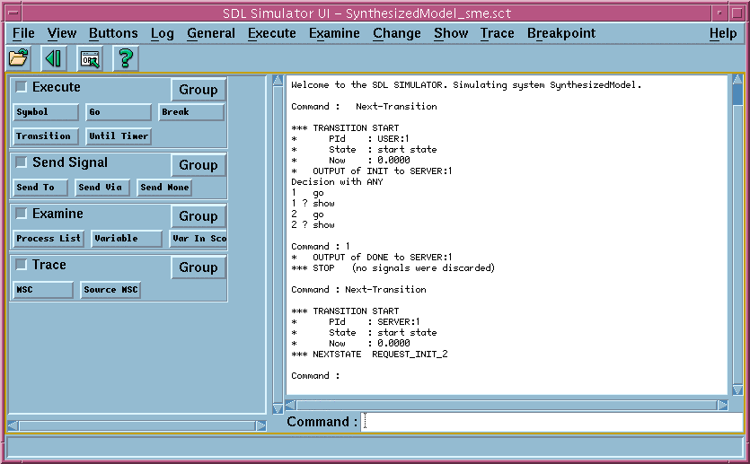
The Tau Simulator UI window has a buttons panel (left), a text output panel (right) and a command entry field (bottom). The text output panel displays the execution trace. The Tau Simulator is an interface to the automatically synthesized executable model produced by the KLOCwork MSC to SDL Synthesizer.
The model consists of several concurrent processes (one for each instance in the input MSC model). The processes exchange signals, in accordance with the input MSC. Each process in the synthesized model performs transitions between internal states.

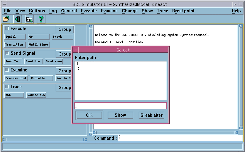
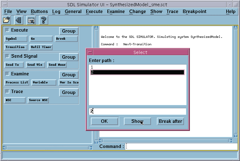
The input MSC model is non-deterministic because it does not provide enough information about the logic behind the actions of the User. According to the model, the User can either send the Request message or the Done message to the Server. The model does not specify how the User makes the choice between these two messages. The KLOCwork MSC to SDL Synthesizer propagates this non-determinism to the executable model. The Telelogic Tau Simulator uses the Path Selection dialog to ask the user which of the alternatives of a non-deterministic choice to take.

The Tau MSC Editor appears and the corresponding message is highlighted.

No process instance scheduled for a transition". This complete Simulator trace is presented below. The trace consists of 4 transitions (from the line "*** TRANSITION START" to the line "*** NEXTSTATE "). Transitions are performed by different instances of the MSC model (see the name of the instance in the second line in each transition section after the keyword PId). The transition section also contains the input signal, or the transition trigger (see the name of the input signal in the fourth line of transition section after the keyword Input). Welcome to the SDL SIMULATOR. Simulating system SynthesizedModel.
Command : Next-Transition
*** TRANSITION START
* PId : USER:1
* State : start state
* Now : 0.0000
* OUTPUT of INIT to SERVER:1
Decision with ANY
1 go
1 ? show
2 go
2 ? show
Command : 1
* OUTPUT of DONE to SERVER:1
*** STOP (no signals were discarded)
Command : Next-Transition
*** TRANSITION START
* PId : SERVER:1
* State : start state
* Now : 0.0000
*** NEXTSTATE REQUEST_INIT_2
Command : Next-Transition
*** TRANSITION START
* PId : SERVER:1
* State : REQUEST_INIT_2
* Input : INIT
* Sender : USER:1+
* Now : 0.0000
*** NEXTSTATE A_LOOP_1
Command : Next-Transition
*** TRANSITION START
* PId : SERVER:1
* State : A_LOOP_1
* Input : DONE
* Sender : USER:1+
* Now : 0.0000
*** NEXTSTATE REQUEST_INIT_2
Command : Next-Transition
No process instance scheduled for a transition

In this part of the exercise we demonstrated how to use the KLOCwork MSC to SDL Synthesizer to simulate MSCs. We explored the behavior of our MSC model using the textual trace of the Telelogic Tau Simulator UI.
In the next two parts of this exercise we will explore more powerful ways to visualize execution traces using the KLOCwork MSC to SDL Synthesizer and Telelogic Tau.