Create MSC and HMSC diagrams in Telelogic Tau
In this exercise, we use Telelogic Tau graphical editors to create our scenario model.
- Start Telelogic Tau with the KLOCwork MSC to SDL Synthesizer (you may need to consult Telelogic Tau documentation and the KLOCwork MSC to SDL Synthesizer Reference Manual). You see the Telelogic Tau Organizer with the MSC to SDL menu.
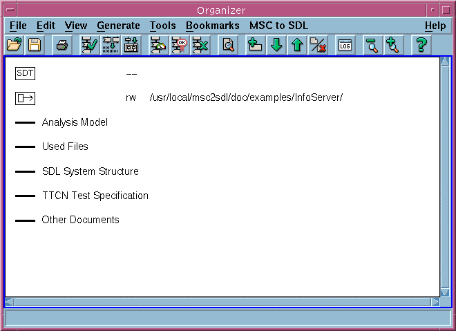
- Create an Organizer module, which serves as the folder for all diagrams in this example. To do this, from the Edit menu, select Select Add New, then select the Organizer radio button and make sure that the corresponding pull-down menu reads Module. Type the name InfoServer into New document name field. The icon for the new module appears in the Organizer view.
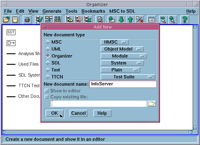
- On the Add New dialog, click the Show in editor checkbox to ensure that you will be able to see the icons for new MSC diagrams.
- Create a new MSC diagram called Request_Init. To do this, from the Edit menu, select Add New, then select the MSC radio button. The corresponding pull-down menu should read MSC. Type the name Request_Init into New document name field. The icon for the new MSC diagram appears in the Organizer view and the Telelogic Tau MSC Editor opens. You can also start the MSC Editor by from the Organizer Tools menu (choose Editors, then MSC Editor).
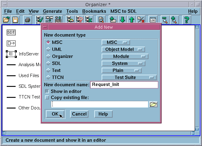
- Create an HMSC diagram by adding a new diagram using the Organizer or the HMSC Editor:
From the Organizer Edit menu, select Add New, then check the MSC radio button and set the corresponding pull-down menu to HMSC.
or
Start the HMSC Editor (from the Tools menu, select Editors, then HMSC Editor).
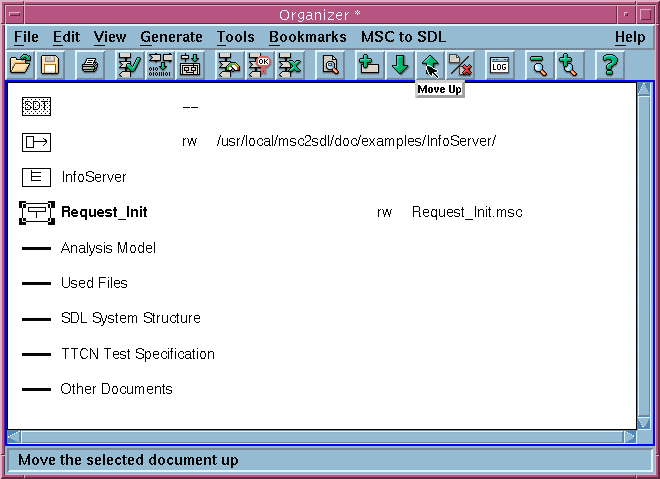
- Move the MSC diagram Request_Init into the Organizer module InfoServer by selecting the icon Request_Init and then clicking the Move up button in the quick button bar of the Organizer.
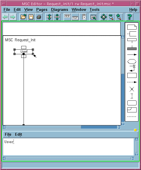
The following figure shows the Telelogic Tau MSC Editor after one instance has been created.
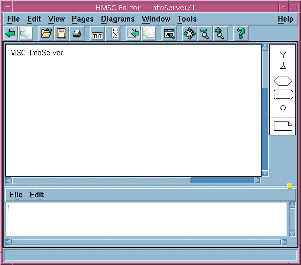
The following figure shows an empty Telelogic HMSC Editor.
- Add a new symbol in the MSC Editor using the palette of graphical symbols (right panel). Click on a symbol in the palette, then point at the graphical area to insert selected symbol.
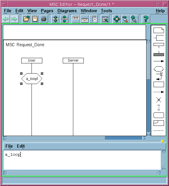
The following figure shows MSC Request_Done after we added two instances and a condition symbol a_loop. A new condition symbol is always added as a local condition (attached to a single instance).
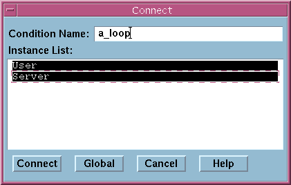
- To create a global condition symbol you need to select the condition symbol in the diagram, then open the Connect dialog (Edit menu, select Connect) and click on the Global button. You can also use this menu to fine tune which instances share this condition. Clicking on an instance in the Instance List on the Connect dialog toggles sharing. After toggling the desired instances, click Connect.
You may need to consult Telelogic Tau documentation for more information about using the graphical editors.
- Create MSC diagrams with the names Request_Init, Request_Data, and Request_Done and HMSC diagram InfoServer. See Model: Information Server.
- Save your work by clicking the Save button in the Organizer. You are prompted to save each diagram and the so-called system file. Save all files in your working directory.
Summary
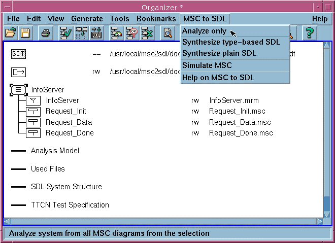
In this exercise we created the Organizer module containing the three MSC diagrams (Request_Init, Request_Data and Request_Done) and an HMSC diagram InfoServer. You used the Telelogic Tau Organizer, MSC Editor and HMSC Editor. The Organizer window should look similar to this one:
Summary
In this exercise we demonstrated how to use the Telelogic Tau Organizer and graphical editors to create the MSC model.
In the next exercise we will use the KLOCwork MSC Analyzer to check the correctness of MSC models.


